- FirstAp
- RegAddr
- Status
- Arith
- MidGoto
- LowGoto
- CondJump
- VarMani
- VarArray
- StackOps
- FirstCal
- StakCall
- CallBUp
- Table0
- ArbTable
- SmallTbl
- StateMC
- LEDOn
- Current Consumption Check
- Debounce
- PinChg
- TimeEnd
- Decouple
- WDT
- PowerUp
- Reset
- TMR0
- Random
- Sleep
- DiffOsc
- EEPROM
- SHORT
- ADCLess
- ADC
- VLadder
- PWMOut
- Cylon
- TMR0Int
- LEDPWM
- IntDeb
- TrueRS
- BasicRS
- SimpRS
- 3RS
- Debug
Useful Code Snippets and Macros

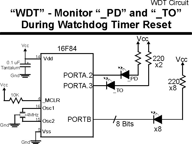
"WDT" Experiment
One of the things that seems to cause problems for most new PICmicro application developers. In the text, I have pointed out that the Watchdog Timer ("WDT") is often enabled by setting a bit in the configuration register and by leaving the _WDT_OFF out of the __CONFIG statement will usually result in the WDT being enabled and resetting the application at either 18 msecs or 2.3 seconds. This can be somewhat hard to find and debug (especially if it is one of your first applications). This experiment demonstrates the WDT timer operation using the previous experiment's code (Decouple) as a basis.
The experiment uses the circuit shown below:
The parts needed for this experiment are listed in the table:
| Part | Description | Required for the YAP-II/EMU-II? |
|---|---|---|
| PICmicro® MCU | PIC16F84-04/P PIC16F877-04/P |
In Socket |
| Vdd/Vss Decoupling Capacitor | 0.1 uF (Any Type) | No |
| _MCLR Pull Up Resistor | 10K, 1/4 Watt | No |
| 4 MHz Ceramic Resonator | Three Leaded Ceramic Resonator with Built in 27-33pF Capacitors | No |
| PORTB LED Current Limiting Resistors | 10x 220W, 1/4 Watt | No - "LED1" Used |
| PORTA/PORTB LED | 10 LED "Bargraph" Recommended | No - "LED1" through "LED9" Used |
| Breadboard | Any Type | No |
| +5 Volt "Vcc" Power Supply | Any Type | No |
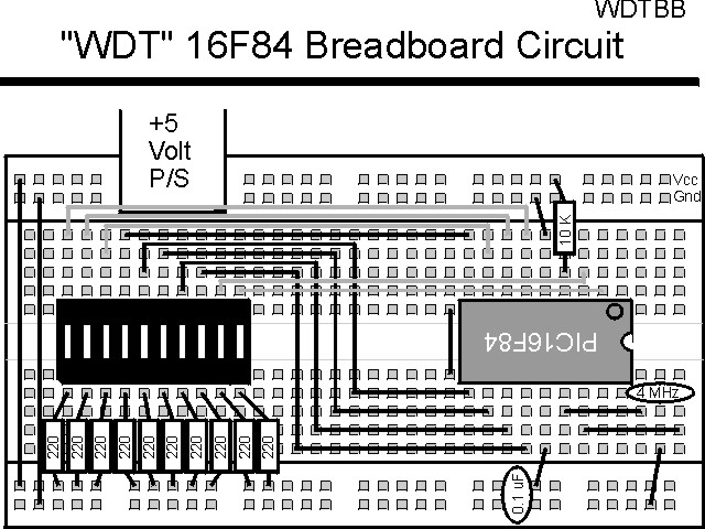
Using a breadboard, the experiment is wired using the guide:
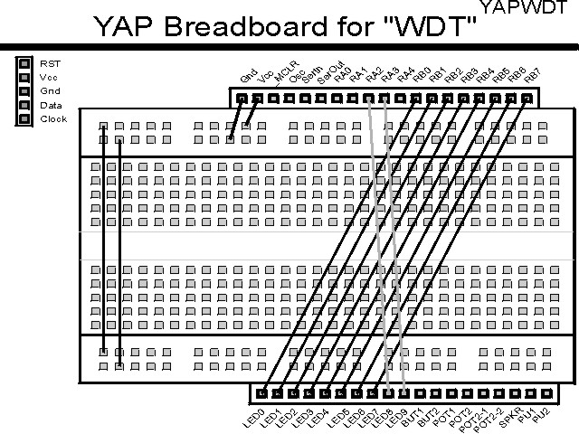
If the EMU-II or YAP-II is used, the experiment is wired as:
The source code listed below can be accessed from the CD-ROM by clicking Here.
 title  "WDT - Demonstrate PICmicro Reset using WatchDog Timer"
;
;  This Code Puts a changing value into a PICmicro's PortB after
;   loading PortA bits 2 and 3 with the _TO and _PD bits.
;
;  The PICmicro should be reset during execution by the operation
;   the Watchdog timer, which will cause the _TO and _PD Display
;   To Change.
;
;
;  Hardware Notes:
;   PIC16F84 Running at 4 MHz
;   _MCLR is Pulled Up
;   All 8 bits of PortB are Pulled up and Connected to LEDs
;   PORTA.2 is Pulled up and Connected to a LED for _PD
;   PORTA.3 is Pulled up and Connected to a LED for _TO
;
;  Myke Predko
;  99.12.23
;
  LIST R=DEC
 ifdef __16F84
  INCLUDE "p16f84.inc"
 else
 ifdef __16F877
  INCLUDE "p16f877.inc"
 endif

;  Register Usage
 CBLOCK 0x020                   ;  Start Registers at End of the Values
BValue
Dlay:2
 ENDC


 PAGE
 ifdef __16F84
 __CONFIG _CP_OFF & _WDT_OFF & _XT_OSC & _PWRTE_ON
 else
 __CONFIG _CP_OFF & _WDT_OFF & _XT_OSC & _PWRTE_ON & _DEBUG_OFF & _LVP_OFF & _BODEN_OFF
 endif

;  Mainline of WDT
  org    0

  nop

  movlw  0x0FF
  movwf  PORTB
  movwf  BValue

  movlw  0x00C
  movwf  PORTA

  bsf    STATUS, RP0
  clrf   TRISB ^ 0x080		;  Make All 8 PortB Bits Output
  movlw  0x013			;  Make RA2 and RA3 Outputs
  movwf  TRISA ^ 0x080
  bcf    STATUS, RP0

  rrf    STATUS, w		;  Get the Status Bits
  xorlw  0x00C			;  Invert _PD and _TO
  andlw  0x00C			;  Clear the Other Bits
  movwf  PORTA			;  Set the LEDs Appropriately

Loop				      ;  Loop Here

  call	 Delay

  bcf    STATUS, C		;  Change PORTB
  btfss  BValue, 7
   bsf   STATUS, C
  rlf    BValue, w
  movwf  PORTB
  movwf  BValue

  call   Delay

  movlw  0x0FF			;  Turn OFF LEDs
  movwf  PORTB

  goto   Loop

Delay				;  Delay 1/5 Seconds
  clrf   Dlay
  clrf   Dlay + 1
  decfsz Dlay, f
   goto  $ - 1
  decfsz Dlay + 1, f
   goto  $ - 3

  return


  end
The rule to take from this experiment is, that if the application does not respond at all or if it resets ever few moments, then check to see whether or not the WDT is inadvertantly enabled.